A touch of safety
Published by Harleigh Hobbs,
Editor
World Coal,
Earth fault limited power reticulation networks are common in underground coal mining jurisdictions that have adopted standards and electrical practices deriving from mining in the UK. These electrical protection standards and guidelines often prescribed minimum or set parameters for the protection schemes. In many instances, key electrical parameters for underground distribution networks are mandatory, or are so ingrained in accepted practice that they are rarely altered.
Whilst mandatory limits to settings or protection parameters represent a body of knowledge gained from experience, they were never intended to be universal or unaltered as load technology and electrical equipment changed over time. Modern electrical loads (such as variable speed drives) demand protection settings and protection equipment that were never envisaged when common protection parameters were prescribed. There is a universal requirement to control touch potential under normal operating and fault conditions, which requires analysis and system design, not blind application of rules of thumb for protection settings.
Protection is a specialised area of electrical engineering. The detail contained within this article is simplified illustrative examples of the principles involved for earth fault limited networks. In all instances, specialist advice should be sought in regard to protection systems and parameter settings.
Protection fundamentals
Mining electrical systems have evolved various protection systems due to their unusual environments, equipment they use and the hazards they present. A typical earth fault limited network will include:
- Earth fault current limitation, usually consisting of a resistor connected between the supply transformer star point and earth (the Neutral Earth Resistor [NER]).
- Earth continuity monitoring and protection.
- Earth leakage protection.
- Earth fault lockout protection.
An element of the electrical protection scheme design is invariably intended to ensure that when people are exposed to touch potentials, the level of voltage and time they are exposed to before protection systems trip is limited to an acceptable level. What constitutes acceptable levels varies by jurisdiction, but within Australian mining applications it is defined by AS/NZS 4871.1:2012 for 50 Hz touch voltages (Figure 1). A properly designed protection system also limits the risk of fire, arcing and hazardous arcing faults, but this is a secondary aim. To ensure the touch potentials are managed to acceptable levels, the complete electrical system needs to be assessed and a protection scheme implemented accordingly.
Touch potentials – what is safe?
Electrical protection in most earth fault limited networks that is used in underground mining applications is designed for indirect contact scenarios (that is, coming into contact with a conductive part that becomes electrically live due to a fault inside a machine or enclosure). For indirect contact scenarios, the majority of the fault current will travel through the cable earth. Only a small fraction of the fault current will flow through the person in contact with the live conductive part and the physical earth.
Figure 1 shows the maximum duration of human exposure to prospective touch voltages that do not usually result in harmful physiological effects. This graph includes two curves that define fibrillation limits under normal conditions (the person is wearing dry clothing and boots and the environment is not excessively wet) as well as wet conditions (contact impedance is low, bare feet, bare hands and a wet environment).

Figure 1. AS/NZS4871.1:2012 – The maximum duration of human exposure to prospective touch voltages that do not usually result in harmful physiological effects.
Note that these curves represent the 50 Hz voltage/time duration limits for the majority of the population that will not result in fibrillation (and so electrocution). They are well beyond the threshold of perception and, at a minimum, will result in a painful shock, involuntary movement and loss of normal muscle control that may result in substantial injury as a consequence. They may only be considered ‘safe’ in that the majority of people are unlikely to fibrillate and will recover from the shock without assistance or lasting physiological damage.
Touch potential analysis
Consider the example where an earth fault occurs in a mobile machine with rubber tyres powered by a trailing cable; this scenario is shown in Figure 2. The earth fault current will flow through the fault to the machine frame and return to the supply transformer star point via the trailing cable earth conductors (primarily). The voltage drop caused by this earth fault current flowing through the total earth impedance will result in a potential rise above earth for the frame of the machine, and it is this potential rise that presents the touch potential hazard. The system assessment must determine the earth fault limitation current and earth continuity relay trip settings that will protect personnel based on the achievable earth leakage clearance times, knowledge of the cable lengths and the resulting pilot and earth impedances.

Figure 2. AS/NZS4871.1:2012 – the indirect contact fault scenario for an earth fault limited system.
Consider a simple example:
For a 1000V system, with earth fault limitation at 2A, the phase to earth voltage is 577V, and the NER impedance will be approximately 288Ω.
An earth continuity relay measures the pilot-earth loop impedance through the pilot termination. This loop impedance includes both the pilot resistance as well as the resistance of the termination device and the return earth resistance.
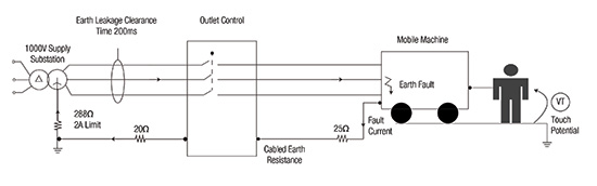
Figure 3. Pilot earth loop.
The touch potential is, of course, generated by the fault current flowing through the return earth impedance, not the pilot or termination impedance. Unfortunately the continuity relay is unable to distinguish the earth return impedance itself, and can only measure the total loop impedance. Worse case is a short cable and so the pilot resistance is very low. In this case, the earth continuity relay will only trip if the return earth impedance is relatively high. Consider an earth continuity trip setting of 70Ω with a short cable and load powered from a restrained receptacle. If we allowed a pilot resistance of (say) 5Ω, a termination impedance of 20Ω, then the earth continuity relay would only trip when the earth return impedance exceeded 45Ω. Referring to Figure 4, the worst case touch potential under a bolted earth fault is:

At 78V the total protection clearance time must be approximately 300 ms, as shown in Figure 4. This duration needs to take into account the relay setting plus the time it takes the contactor to actuate. If the total clearing time exceeds 300 ms, the impedance of the NER or the earth continuity limit must be adjusted to ensure the touch potential is below the fibrillation limit.
Often the protection relay does not operate the contactor or breaker directly. Operating delays of the contactor and interposing relays add to the protection relay actuation time. If the total clearance time for outlet included:
- Earth leakage relay 200 ms.
- Interposing relay delay 20 ms.
- Breaker/contactor delay 130 ms.
The total clearance time might be of the order of 350 ms. As shown in Figure 3, this would result in a touch voltage that is beyond the wet area fibrillation limit.

Figure 4. Resulting touch voltage for a 350 ms clearance time.
For a clearance time of 350 ms, a touch potential of 60V would be at the fibrillation limit.
Note also that many earth continuity relays automatically compensate for the resistance of the pilot terminating element or diode. In the preceding example, the maximum touch potential is considerably higher if the trip setting of 70Ω represents only the pilot resistance (relatively low on a short cable run) and earth return resistance.
Observations
The majority of earth faults in an earth fault limited network generate a hazardous touch potential and we are reliant on active protection to clear a fault for personnel safety.
The presence of an NER and relatively low fault current limit does not make a system safe.
Maintenance practice must ensure earth leakage protection properly resolves leakage current (in terms of magnitude and frequency) to ensure active protection is functional. If this active protection fails to operate the 50 Hz, wet area touch potential must be restricted to less than 25V to remain below the fibrillation limit.
There are three parameters that directly affect touch potential in an earth fault limited system. These parameters cannot be set independently or altered without considering the resultant effect on touch potential:
- The impedance of the NER.
- The total earth leakage clearance time.
- The earth continuity limit.
Increasing the earth leakage clearance time to reduce instances of nuisance tripping directly affects the duration of touch potential that must remain below the fibrillation limit.
Increasing the earth leakage trip current increases the potential power dissipation in the fault, and so increases fire risk. It also reduces the ability of the protection system to detect a high impedance fault.
It must be possible to demonstrate protection settings that result in touch potentials that are as low as reasonably practical. It is not sufficient to blindly follow rules of thumb or accepted practice. Protection settings must be justified by calculation and system design.
The Ampcontrol AUK1000
The Ampcontrol AUK1000 includes a sophisticated fully programmable protection system that allows many protection parameters to be independently set and adjusted. This allows the protection settings to be adapted to optimally suit a wide variety of applications. For example, earth leakage trip time can be adjusted from 50 ms to 500 ms, allowing grading of cascaded relays in time. Provided touch potential is controlled (by appropriate settings of earth continuity and NER selection), sub circuits can be automatically isolated under fault conditions minimising disruption to other equipment fed from the same supply, improving production up time without jeopardising safety. The protection suite includes earth leakage; intrinsically safe earth fault lockout; earth continuity (including remote start mode); contactor failure protection; motor thermal overload protection; short circuit protection; under current protection; current balance protection; and under voltage protection.
Author
Tim Wylie from Ampcontrol.
Note
This article first appeared in World Coal November/December. To read this and much more, register to receive a copy here.
Read the article online at: https://www.worldcoal.com/special-reports/29122017/a-touch-of-safety/
You might also like


Facing East: What India’s steel expansion means for US metallurgical coal
Mustafa Iqbal, Bloor Square Capital, considers how, as India’s blast furnace capacity expands, producers with reserves, costs, and export infrastructure are winning a selective, durable opportunity.